

The TEK Vario
Understanding how a TEK vario works and why it is useful in paragliding.
1 - What is a TEK vario ?
A classic vario calculates climb and sink rates solely from altitude changes. It therefore relies only on changes in potential energy.
A TEK vario also takes into account changes in airspeed (kinetic energy)in addition to altitude changes (potential energy). This is why a compensated variometer is also called a Total Energy variometer (TEK) (total energy = potential energy + kinetic energy).
2 - Why use a compensated variometer?
As pilots, the important information is not simply knowing whether we are climbing, but understanding why we are climbing. Are we gaining altitude because we are in rising air, or because we are performing a pitch-up maneuver?
A paraglider has the particular characteristic of flying while constantly oscillating. These oscillations are caused by all the disturbances encountered during flight, whether from pilot inputs, turbulence, or entering and exiting thermals.
To observe this, you can look at the evolution of airspeed or pitch angle during a flight recorded with the Vector Vario. This data becomes visible by loading the IGC+ file created at the end of the flight into the software Vector Vario Analyser.
Here is an example from a smooth soaring flight in calm conditions.

Oscillations can be observed throughout the entire flight, both in airspeed (top graph) and in pitch angle (bottom graph).
These oscillations, with a period of approximately 7 seconds, indicate continuous exchanges between potential energy and kinetic energy. In other words, the glider periodically trades airspeed for altitude during a pitch-up motion, then immediately regains that speed by converting the gained altitude back into kinetic energy.
The TEK vario, thanks to its airspeed measurement, is able to detect and filter out all those wing oscillations.
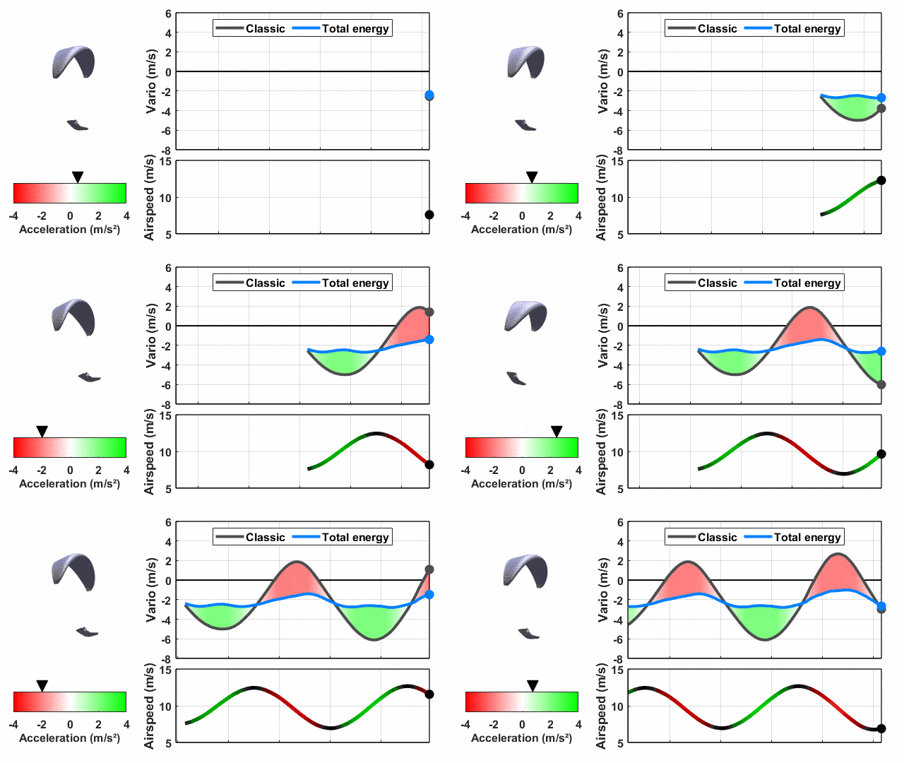
This filtering can be verified by performing a pitch exercise. As shown in the animation below, the compensated vario (blue curve) effectively removes all the pitch oscillations that are visible on the classic vario (black curve).
3 - Why is a TEK variometer useful in paragliding?
When using a classic vario, the paraglider’s natural oscillations (see previous chapter) add to the signals we are actually interested in: lift. This creates noise and therefore interferes with the reading of the air mass movement indicated by a classic vario.
We have all experienced the situation where we fly through a narrow thermal and fail to relocate it after making a half turn. This happens because our mental picture of its position is distorted by the wing’s oscillations. A conventional vario does not indicate the true maximum of the thermal. As a result, we may end up circling beside it and miss its core.
The following diagram illustrates the effect of the oscillations typically experienced in paragliding when crossing a narrow thermal.

When entering the thermal, the paraglider pitches up, creating a positive bias on the classic vario (red curve). A maximum climb indication is therefore detected much too early. Then, as the wing accelerates again, the variometer can drop back to 0 m/s even while flying through the core of the thermal. This is followed by another pitch-up motion, which produces a second false maximum outside the thermal.
By measuring airspeed, the TEK vario eliminates the effects of the wing’s oscillations and allows accurate localization of the thermal core (green curve). This makes thermal detection and centering significantly more efficient.

Of course, this example is intentionally simplified for clarity. In general, the wider and smoother the thermal, the less the wing’s oscillations will interfere with locating its core.
The performance difference between a classicl vario and a TEK vario is therefore most noticeable in weak or turbulent conditions.
4 - Two examples of the difference between a classic and a TEK vario
Example 1: Speed regime change
This is the most intuitive case. When releasing the speed bar, the paraglider performs a pitch-up motion.
The following graph shows an example of speed bar release on a high-performance wing, where the airspeed decreases from 61 km/h to 43 km/h.

As the speed decreases, the classic vario (black curve) indicates a peak of +2 m/s. This peak corresponds to the wing’s pitch-up motion, not to the presence of a thermal. The TEK vario (red curve) filters out this pitch-up effect and therefore does not display this peak.
It can also be seen that the red curve is not perfectly flat either. Small fluctuations remain because
total energy is not perfectly conserved during the oscillations. As the speed decreases, the paraglider’s drag is reduced, causing the compensated variometer reading to rise slightly.
Example 2: Entering a thermal
Here is a case where turbulence at the thermal entry causes a forward surge, followed by an increase in airspeed. Since the entry into the thermal occurs during this acceleration phase, the classic vario (black curve) shows a delay of approximately 1.5 seconds due to the wing’s subsequent pitch-up motion.

We can also observe the persistence of the wing’s oscillations, which generate misleading climb rate of more than 2 m/s on the classic vario, despite the relatively calm conditions (a 1 m/s thermal). The TEK vario (red curve) filters out these oscillations.
5 - The Feel of a TEK Vario
When flying with a classic vario, the audio signal tends to confirm the sensations already felt by the pilot. In other words, the vario often provides information that we already perceive intuitively.
We are so used to this behavior that, paradoxically, flying with a TEK varior for the first time can feel somewhat unsettling.
This is because we are no longer asking the same question. With a classic vario, the question is essentially: “What is the pilot’s vertical movement?” With a TEK vario, the question becomes: " What is the movement of the surrounding air mass? ".
And it is precisely information about the movement of the air mass that allows us to understand our environment, make the most of it, and ultimately fly better.
The compensated vario also provides a steadier indication in turbulent conditions, as it does not overreact to the wing’s oscillatory movements.
Note: Because of the significantly different behavior between a classic vario and a compensated vario, it is not recommended to fly using both at the same time. To compare their differences, it is better to use only one type of vario at a time. The Vector Vario can be used for this test by configuring two audio profiles: one with a compensated vario and the other with a conventional vario. You can then simply switch between the two profiles during the flight.
6 – Going further: why does a paraglider constantly oscillate?
This technical section aims to explain why a paraglider is continuously oscillating, a behavior that is much less visible on other types of aircraft.
To answer this question, we need to look at the longitudinal stability (in the direction of flight) of a paraglider.
6.1 - Introduction
First, we need to correct the common misconception that a paraglider behaves like a simple pendulum, with a mass hanging at the end of a string.
An aircraft rotates around its center of gravity.

In aerodynamics, stability can be described in two ways:
- Static stability.
- Dynamic stability.
To visualize this, we can imagine a spiral spring held vertically by its base at the center of gravity (located just above the pilot), extending upward to the wing.
- Static stability describes the strength of the restoring force that brings the paraglider back toward its original position. It can be seen as the stiffness of the spring.
- Dynamic stability describes how quickly the system returns to its equilibrium position, taking into account inertia and the non-linear behavior of certain forces. For example, if the mass at the top of the spring is large and experiences little aerodynamic damping, the system will oscillate for a long time before stabilizing. Conversely, if the mass is lighter and generates significant aerodynamic drag, the system will exhibit little or no oscillation and will quickly return to a vertical equilibrium position.
6.2 – Forces and moments acting on a paraglider
To estimate the paraglider’s static pitch stability, we first need to analyze the forces and moments acting on the system.
In rigid body mechanics, a force that does not act through the center of gravity creates a rotation of the object. This rotational effect is called a moment (or torque) and corresponds to the force multiplied by its lever arm. The following diagram illustrates this principle for the lift force acting on a paraglider.

In steady flight, the sum of all forces and the sum of all moments are equal to zero (Newton’s laws of motion and the conservation of angular momentum).
Forces acting on the paraglider:
- 1 - Gravity, acting at the paraglider’s center of gravity (slightly above the pilot).
- 2 - Lift, acting at the wing’s center of pressure (approximately 25% of the chord length, although its exact position depends on the airfoil design).
- 3 - Wing drag, also acting at the wing’s center of pressure. Two drag components are involved: profile drag, related to the aerodynamic efficiency of the airfoil; induced drag, which is the aerodynamic cost of generating lift.
- 4 - Line drag, acting approximately at the midpoint of the suspension lines.
- 5 - Pilot and harness drag, acting around the center of volume of the pilot and harness.
Moments acting on the paraglider:
- 1 - Gravity acts through the center of gravity and therefore generates no pitching moment.
- 2 - Lift creates a nose-down pitching moment.
- 3 - Wing drag creates a nose-up pitching moment.
- 4 - Line drag also creates a nose-up pitching moment.
- 5 - Pilot drag creates a nose-down pitching moment.
The following diagram summarizes the forces and moments acting on a paraglider.

6.3 - Static stability
To determine the static stability of an aircraft, we examine how the different forces and moments evolve as the angle of attack changes.
For the aircraft to be stable, an increase in angle of attack must produce a decrease in pitching moment, so that the motion is not amplified.
The following diagram shows a numerical example of how pitching moment varies with angle of attack for a typical paraglider.

This simplified calculation indicates that a paraglider is globally stable, with a static stability (the slope of the curve) of approximately −150 N·m/°. This stability mainly comes from the lift force, which is tilted forward. When the angle of attack increases — for example when entering a thermal — the lift also increases and generates a nose-down pitching moment that opposes the increase in angle of attack.
However, paragliders have a particular characteristic: since the lift force acts on the wing and is not aligned with the center of gravity, the lift lever arm changes with the angle of attack. The following diagram illustrates how the lift force evolves when entering a thermal (increase in angle of attack).

This variation of the lift lever arm makes the stability curve non-linear. The lower the angle of attack becomes, the lower the stability, until it becomes almost nonexistent as the wing approaches collapse conditions.
This non-linearity can be observed through a well-known fact among pilots: paragliders experience collapses regularly, but stalls are comparatively rare. The reason is that a paraglider is much more stable near stall conditions than near collapse conditions..
Notes:
- Since the static stability of a paraglider mainly comes from the lift lever arm, the farther the wing is from the pilot, the more statically stable the system becomes. However, this also increases the moment of inertia, whose consequences will be discussed in the next section.
- The better the glide performance of the wing, the more vertically oriented the lift vector becomes. This reduces the lever arm and therefore decreases static stability.
- Likewise, the smaller the wing chord (that is, the higher the aspect ratio), the smaller the lift lever arm becomes, which also reduces static stability. sera faible, ce qui réduit la stabilité statique.
- On an airfoil, the center of pressure is not perfectly fixed: it moves slightly depending on the angle of attack. On a cambered airfoil, the center of pressure generally moves forward as the angle of attack increases, reducing the lever arm and therefore reducing static stability. Conversely, a reflex airfoil tends to have a more stable center of pressure — or even one that moves rearward as the angle of attack increases — which improves static stability.
6.4 - Dynamic stability
Static stability is an essential property, but it is not sufficient on its own for safe flight. Dynamic stability must also be strong enough so that, after a disturbance, the aircraft returns to its equilibrium position quickly enough to avoid leaving its safe flight envelope.
Dynamic stability is composed of two main elements:
- The moment of inertia opposes the paraglider’s rotational movements. It is a quantity that reflects how mass is distributed within an object. The farther the mass is from the center of gravity, the greater the moment of inertia becomes, and the more difficult it is to rotate the object. The interaction between the moment of inertia and the pitching moment (which is statically stable) creates a persistent oscillatory motion. The greater the moment of inertia, the longer the oscillation period becomes, since the system takes more time to return to its equilibrium position.
- The damping coefficients dissipate — or in some cases amplify — the oscillations generated by the interaction between inertia and pitching moment. On a paraglider, these damping effects mainly come from the aerodynamic response of the wing during dynamic flight phases. These aerodynamic effects are stabilizing and generally strong enough to prevent oscillations from persisting indefinitely.
Using the moment of inertia and the static stability, it can be estimated that the characteristic oscillation period of a paraglider is on the order of 1 to 2 seconds. Since the damping coefficients dissipate these oscillations very quickly, this characteristic time also corresponds approximately to the time required for the paraglider to return to its equilibrium angle of attack after a disturbance. It is during this recovery phase that the paraglider may leave its normal flight envelope. This is why good dynamic stability is directly linked to safety.
Note: Static stability increases linearly with the distance between the pilot and the wing, whereas the moment of inertia increases with the square of that same distance. As a result, the longer the suspension cone, the more dominant the moment of inertia becomes, which reduces dynamic stability. The wing therefore takes longer to return to its equilibrium position, increasing the probability of the wing leaving its normal flight envelope.
6.5 -The phugoid Mode
The previous dynamic stability calculations indicate a characteristic response time on the order of one second and without sustained oscillations. The oscillations observed in flight, with a period of approximately 7 seconds, therefore arise from a different phenomenon.
Il s’agit d’oscillations de type phugoïde.
In a phugoid motion, the paraglider flies with a constant angle of attack. What we observe are exchanges between potential energy and kinetic energy. It can be broken down as follows:
- 1 - The paraglider is on a climbing trajectory: it gains altitude, but without an engine its airspeed decreases.
- 2 - The airspeed eventually becomes too low to balance the force of gravity, and the paraglider transitions into a descending trajectory.
- 3 - During the descent, the paraglider’s airspeed increases until lift is balanced again. The wing returns to steady flight, but on a descending trajectory, so it continues to lose altitude while the airspeed keeps increasing.
- 4 - At a certain point, the lift force becomes strong enough to stop the descending trajectory and initiate a new climbing trajectory. And the cycle repeats…

The phugoid motion is triggered by a disturbance in the force equilibrium, which induces a change in the flight trajectory.
The longer the force imbalance lasts, the larger the amplitude of the phugoid oscillation becomes. As explained in the previous section, it is dynamic stability that allows this temporary force imbalance to exist. Therefore, the stronger the dynamic stability of a paraglider (that is, the shorter its response time), the less the trajectory will deviate and the less the phugoid mode will be excited.
A phugoid oscillation dissipates more or less rapidly, mainly because of drag. However, due to the many disturbances encountered throughout the flight and the relatively small airspeed variations involved (around 20% of the flight speed, which produces little dissipation), this oscillation is almost always present.
Notes:
The period of phugoid oscillation does not depend on the length of the riser line cone. It can be estimated from the ratio between flight speed and gravitational acceleration. For a paraglider flying at 10 m/s, we obtain a period of 2πV/g=6.4 seconds. In practice, a slightly higher value is observed, between 6.4 and 7 seconds, whether for a mini wing or a tandem glider.
6.6 - How a phugoid oscillation is triggered
We now have the key concepts needed to describe what happens when flying a paraglider.
Let us return to the case of entering a thermal:
- 1 – We are in stabilized flight and enter a thermal. The angle of attack increases.
- 2 - The dynamic stability of the paraglider compensates for this increase in angle of attack within 1 to 2 seconds.
- 3 – Meanwhile, our excess angle of attack generates surplus lift. The paraglider then follows an upward trajectory, while also pitching forward to reduce its angle of attack.
- 4 - Once the angle of attack has returned to normal, the paraglider is already established on a climbing trajectory. A phugoid oscillation has now been initiated.
- 5 - This mechanism repeats with every turbulence encounter, thermal entry, or pilot input, continuously sustaining the phugoid motion, which is the oscillation observed in paragliding.

A similar sequence occurs when exiting a thermal, when a decrease in angle of attack is experienced. The phugoid is then initiated with a downward trajectory, which can give the impression of encountering a descending air mass.
6.7 - Conclusion
Throughout this chapter, we have seen that paraglider oscillations are of the phugoid type.
Their large amplitude in paragliding is explained by the wing’s relatively low dynamic stability: the response time required to correct a variation in angle of attack is generally between 1 and 2 seconds, giving the phugoid oscillation enough time to develop.
Since the phugoid is an oscillation resulting from exchanges between potential energy and kinetic energy, the compensated variometer is the ideal tool for filtering it out and thus better analyzing the actual movements of the surrounding air mass.